Buzzers

In the Mindev kit we've attached 2 different buzzers that utilizes two main technologies. Each technology has specific advantages and tradeoffs that must be taken into consideration depending on the application requirements.
In this lesson we'll learn how to use and control the buzzer and what's the electronic principles of the buzzer is working on, at the end you'll be able to use the active buzzer to play basic on/off buzzing noise and the passive buzzer to play a nice melody!
Features
There are 2 different buzzer types: Piezo buzzer and Magnetic buzzer, let's take a look at each of their features.
Piezo buzzer (Active buzzer)
- Wide operating voltage: 3~250 V
- Lower current consumption: less than 30 mA higher rated frequency
- Larger footprint
- Higher sound pressure level
Magnetic buzzer (Passive buzzer)
- Narrow operating voltage: 1~16 V
- Higher current consumption: 30~100 mA
- Lower rated frequency
- Smaller footprint
- Lower sound pressure level
Hardware explained
As we've mentioned we've included 2 different buzzers with the kit, let's walk on each buzzer principles to understand how it works and what drives it to make that buzzing noise we all like to hear.
Piezo buzzer (Active buzzer)
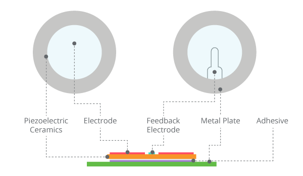
At the heart of the piezo-type buzzers there is the piezoelectric element. Piezoelectric element is composed of a piezoelectric ceramic and a metal plate held together with adhesive. Both sides of the piezoelectric ceramic plate contain an electrode for electrical conduction. Piezo materials exhibit a specific phenomenon known as the piezoelectric effect and the reverse piezoelectric effect. Exposure to mechanical strain will cause the material to develop an electric field, and vice versa.
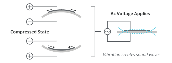
When an alternating voltage is applied to the piezoceramic element, the element extends and shrinks diametrically. This characteristic of piezoelectric material is utilized to make the ceramic plate vibrate rapidly to generate sound waves.
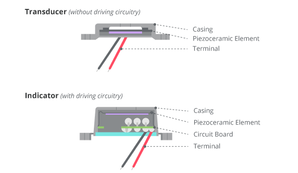
There are two types of piezo buzzers - transducers and indicators. Transducers consist of a casing, a piezoceramic element and a terminal. In order to operate a transducer, the user must send a square wave signal to the buzzer. Indicators consist of a casing, a piezoceramic element, a circuit board and a terminal. In order to operate an indicator, the user must send the buzzer a specified dc voltage.
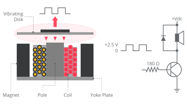
Magnetic buzzer (Passive buzzer)
The illustration below highlights the structure of a typical magnetic buzzer. Like piezo technology, magnetic buzzers are available in transducer and indicator configurations. In a magnetic buzzer, the transistor acts as the driving circuit. Indicators include the transistor, creating a tone when a dc voltage is applied. Transducers lack this transistor, requiring a square wave signal to operate properly.
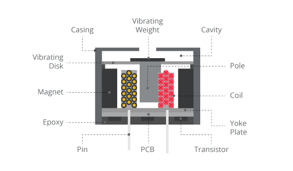
The vibrating disk in a magnetic buzzer is attracted to the pole by the magnetic field. When an oscillating signal is moved through the coil, it produces a fluctuating magnetic field which vibrates the disk at a frequency equal to that of the drive signal.
Diagrams
After we've learned about the buzzer types and elements, it's time to connect the buzzer to our microcontroller and get it going. depends on what controller you are using (such as Raspberry Pi, Arduino, ESP etc ..) you'll need different diagrams. below we'll show you how to attach the buzzer in different diagram to a different controller.
Raspberry Pi wiring diagram
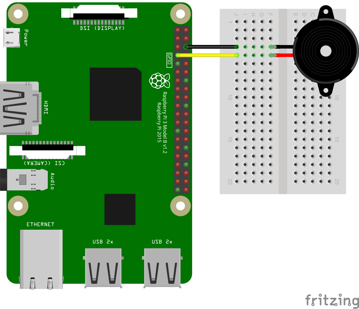
As the Raspberry Pi diagram shows, our buzzer have 2 wires one is GND and one is VCC, the VCC can be controlled by 3.3V which means we can connect it to the GPIO pins directly. In our Diagram we choose to connect the VCC pin of the buzzer to the Raspberry Pi GPIO4 pin. The black wire (GND) from the buzzer go to the ground pin on the raspberry pi.
Arduino wiring diagram
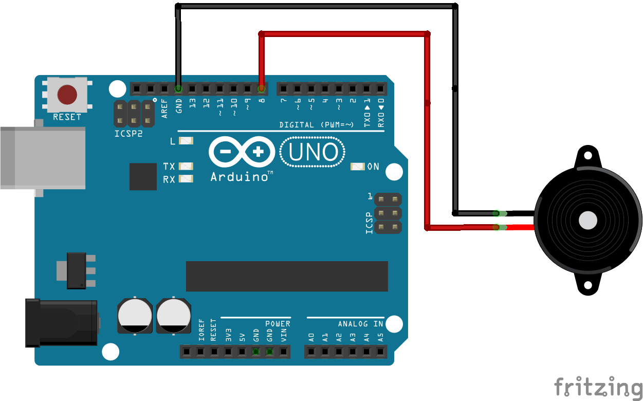
Similar to the raspberry Pi diagram, in the Arduino diagram our buzzer also have 2 pins (obviously). For the Arduino we'll connect the positive (VCC) pin from the buzzer to the Digital Pin number 8 on the Arduino while the negative pin (GND) will go to the ground pin on the Arduino, that way we can output digital signal to the Arduino and control the buzzer similar to the Raspberry Pi GPIO principle.
ESP32 / ESP8266 wiring diagram
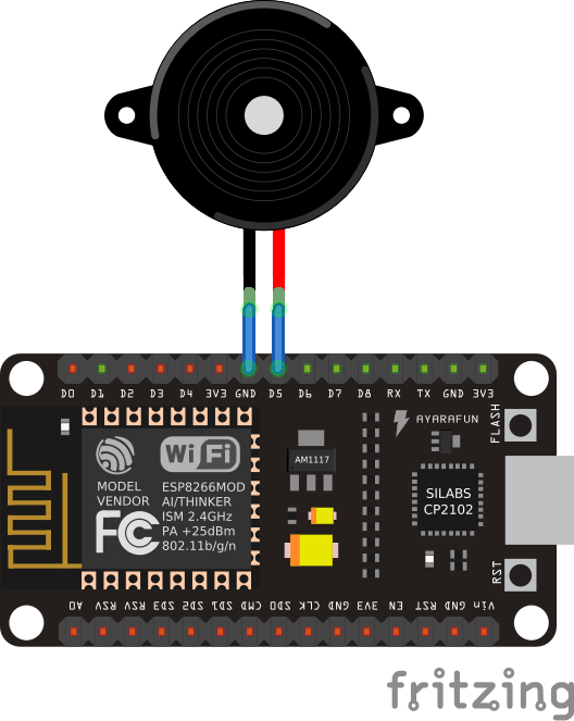
For the ESP we'll connect the positive wire from the buzzer to D5 (digital 5) pin on the ESP board while connecting the GND wire from the buzzer to the ground point in order to close the circuit, the same principle goes here and when controlling the buzzer we always use digital output pins.
Software explained
Let's show an example of the 2 different buzzers, one is the active buzzer to create a simple buzzing noise and the other one is the passive buzzer which we can use to play music with by playing it using a specific frequency.
Piezo buzzer (Active buzzer)
The piezo buzzer is fairly easy as we just need to supply 3.3-5V to it and it will work right away, we can use GPIO pins in raspberry pi or IO pins in ESP or just digital pins in Arduino, all will work perfectly fine.
Example code
The code is very straight forward and available for all the platforms
#!/usr/bin/python
# -*- coding: utf-8 -*-

import RPi.GPIO as GPIO
import time

buzzer_pin = 4

GPIO.setmode(GPIO.BCM)
GPIO.setup(buzzer_pin, GPIO.OUT)

# Make buzzer sound
GPIO.output(buzzer_pin, GPIO.HIGH)
time.sleep(0.5)
# Stop buzzer sound
GPIO.output(buzzer_pin, GPIO.LOW)

GPIO.cleanup()
import machine
import time

# define buzzer on pin IO5 (digital 5) as OUTPUT
buzzer = machine.Pin(5, machine.Pin.OUT)
# define sleep interval as 3 seconds
sleep_interval = 1

# turn on the buzzer
buzzer.value(1)
# wait for the defined sleep interval
time.sleep(sleep_interval)
# turn off the buzzer
buzzer.value(0)
// define buzzer on pin IO5 (digital 5) as OUTPUT
const int buzzer = 5;

void setup() {
  pinMode(buzzer, OUTPUT); // Set buzzer - pin 5 as an output
}

void loop() {
  // turn on the buzzer
  digitalWrite(buzzer, HIGH);
  Serial.println("Buzzer is HIGH");
  delay(1000);
  // turn off the buzzer
  digitalWrite(buzzer, LOW);
  Serial.println("Buzzer is LOW");
  delay(1000);
}
const int buzzer = 8; //buzzer to arduino pin 8

void setup(){
  pinMode(buzzer, OUTPUT); // Set buzzer - pin 8 as an output
}

void loop(){
  tone(buzzer, 1000); // Send 1KHz sound signal...
  delay(1000);        // ...for 1 sec
  noTone(buzzer);     // Stop sound...
  delay(1000);        // ...for 1sec
}
Magnetic buzzer (Passive buzzer)
For this example we'll be taking a .midi file and converting it to Arduino / Raspberry Pi code to allow us to play a song using the Magnetic buzzer. To do it, we'll download a custom midi file and we will use a website to convert the midi file to code.
For the Raspberry Pi example we'll need to use the software PWN (not the normal GPIO we've used earlier with the active buzzer) this is due to the passive buzzer characteristic that requires square waves in order to operate it and not just a constant DC voltage.
Finding midi file to play
There are a lot of websites that offer free midi files, for our tutorial we'll be using the "Harry Potter theme song" midi file downloaded from here: Harry potter theme song midi file you can download any midi file you want and we will use it later in our conversion process for Arduino / Raspberry Pi code
Example code below uses Harry potter theme midi
The example code below uses the midi file we've downloaded from the link previously given, if you want other tunes you'll need to download your own midi file and convert it manually.
Converting midi to code
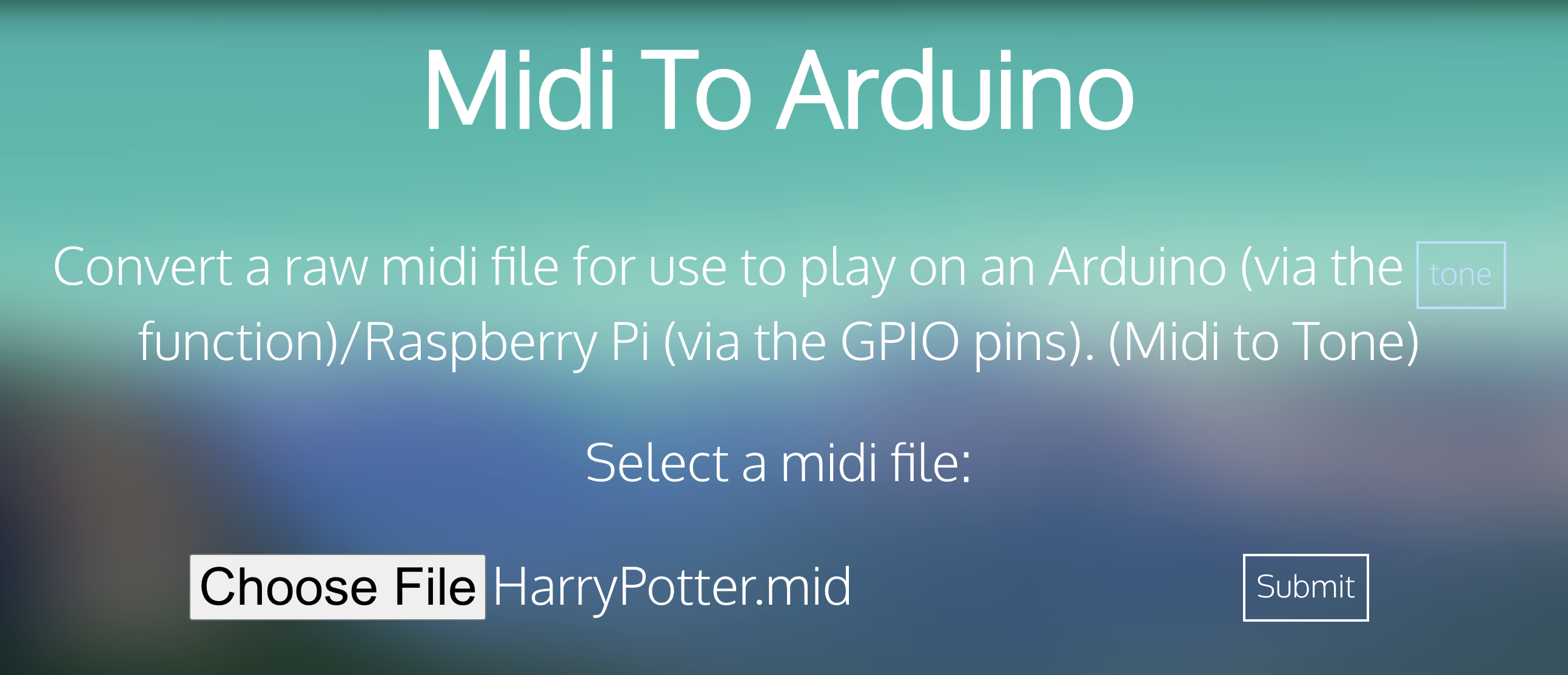
In order to convert the midi file to code we'll use the following free website: ExtraMaster MiDi to Arduino / Raspberry Pi this will allow us to convert any midi file into code in seconds.
First step, download your midi file. once you have it go to the website and upload it, then click submit:
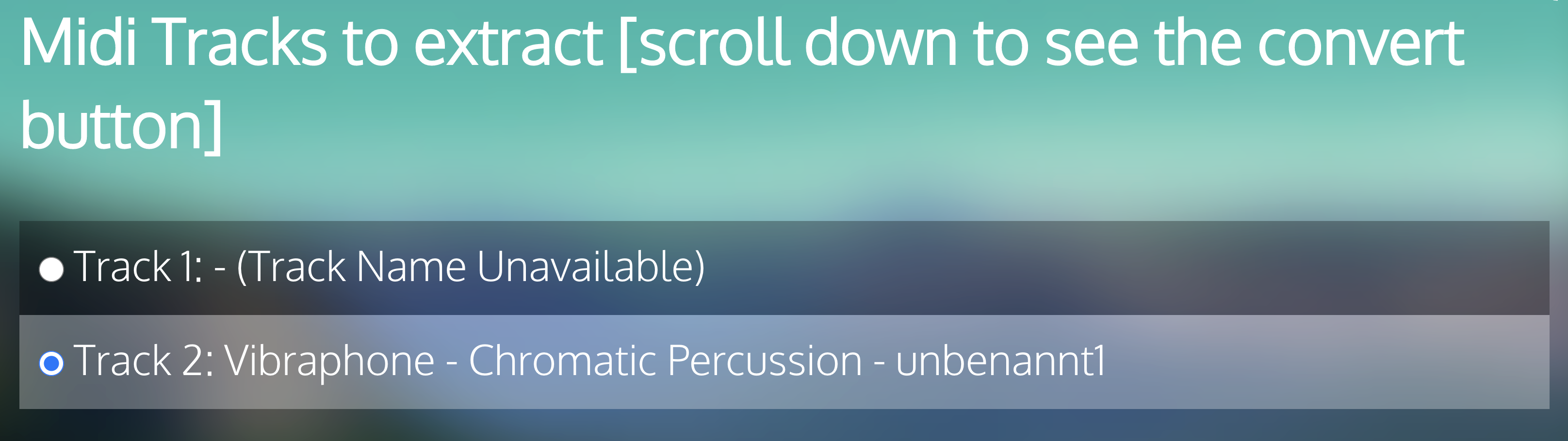
Next step will be to select the midi file to extract, make sure you choose the one that doesn't say "unknown", most often you can leave it as default and there shouldn't be any troubles.
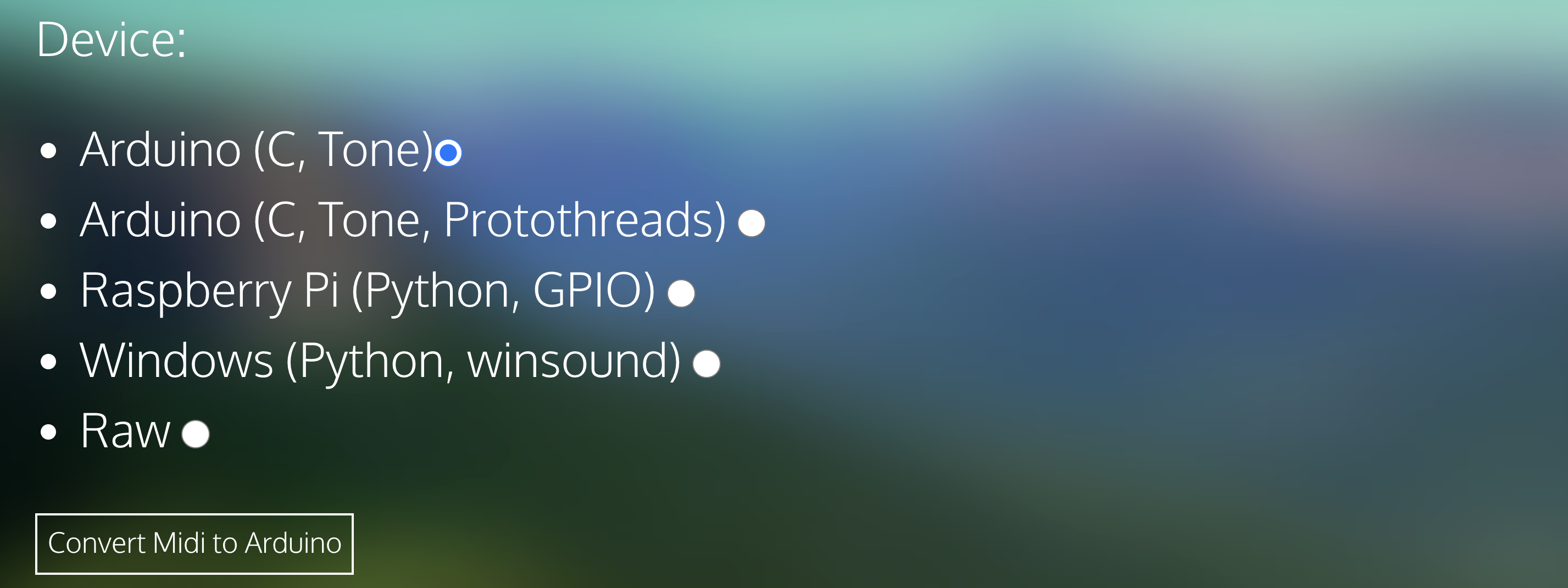
Finally choose the format you want to convert to. do you want to use Raspberry Pi? Arduino? Unfortunately, the website does not offer support to ESP-Arduino or MicroPython but this can be easily solved by small modifications.
For MicroPython modify the Raspberry Pi python code and for ESP-Arduino modify the Arduino C++ Code, this should be fairly easy.
Example code
Below is the example code based on the Harry Potter theme song midi file, if you'd like to use different tune - convert it yourself by using the steps we've explained above.
## Credit:
## Midi to Raspberry Pi Converter
##     - Andy Tran (extramaster), 2015
## https://www.extramaster.net/tools/midiToArduino/
##
## Process:
## Midi -> Midi tracks -> Note mappings -> Frequency
##
## CC0

import RPi.GPIO as GPIO
import time

# Set this to be the pin that your buzzer resides in. (Note that you can only have one buzzer actively using the PWM signal at a time).

# GD = GND = Ground

# RPI v1 GPIO Layout BCM
# 5V 5V GD 14 15 18 GD 23 24 GD 25 08 07
# 3V 02 03 04 GD 17 27 22 3V 10 09 11 GD

# RPI v2 GPIO Layout BCM
# 5V 5V GD 14 15 18 GD 23 24 GD 25 08 07 SC GD 12 GD 16 20 21
# 3V 02 03 04 GD 17 27 22 3V 10 09 11 GD SD 05 06 13 19 26 GD

# Note: Raspberry Pi 2 seems to handle software-PWM a lot better then the original Raspberry Pis.
tonePin = 4

GPIO.setmode(GPIO.BCM)
GPIO.setup(tonePin, GPIO.IN)
GPIO.setup(tonePin, GPIO.OUT)
p = GPIO.PWM(tonePin, 100)

# High-level abstraction of the Arduino's Delay function
def delay(times):
    time.sleep(times/1000.0)

# High-level abstraction of the Arduino's Tone function, though this version is blocking
def tone(pin, pitch, duration):
    if pitch == 0:
        delay(duration)
        return
    p = GPIO.PWM(tonePin, pitch)

    # Change the duty-cycle to 50 if you wish
    p.start(30)
    delay(duration)
    p.stop()

    # Delay used to discourage overlap of PWM cycles
    delay(2)

def midi():
    tone(tonePin, 493, 249.99975)
    tone(tonePin, 659, 374.999625)
    tone(tonePin, 783, 124.999875)
    tone(tonePin, 739, 249.99975)
    tone(tonePin, 659, 499.9995)
    tone(tonePin, 987, 249.99975)
    tone(tonePin, 880, 749.99925)
    tone(tonePin, 739, 749.99925)
    tone(tonePin, 659, 374.999625)
    tone(tonePin, 783, 124.999875)
    tone(tonePin, 739, 249.99975)
    tone(tonePin, 587, 499.9995)
    tone(tonePin, 698, 249.99975)
    tone(tonePin, 493, 1249.99875)
    tone(tonePin, 493, 249.99975)
    tone(tonePin, 659, 374.999625)
    tone(tonePin, 783, 124.999875)
    tone(tonePin, 739, 249.99975)
    tone(tonePin, 659, 499.9995)
    tone(tonePin, 987, 249.99975)
    tone(tonePin, 1174, 499.9995)
    tone(tonePin, 1108, 249.99975)
    tone(tonePin, 1046, 499.9995)
    tone(tonePin, 830, 249.99975)
    tone(tonePin, 1046, 374.999625)
    tone(tonePin, 987, 124.999875)
    tone(tonePin, 932, 249.99975)
    tone(tonePin, 739, 499.9995)
    tone(tonePin, 783, 249.99975)
    tone(tonePin, 659, 1249.99875)
    tone(tonePin, 783, 249.99975)
    tone(tonePin, 987, 499.9995)
    tone(tonePin, 783, 249.99975)
    tone(tonePin, 987, 499.9995)
    tone(tonePin, 783, 249.99975)
    tone(tonePin, 1046, 499.9995)
    tone(tonePin, 987, 249.99975)
    tone(tonePin, 932, 499.9995)
    tone(tonePin, 739, 249.99975)
    tone(tonePin, 783, 374.999625)
    tone(tonePin, 987, 124.999875)
    tone(tonePin, 932, 249.99975)
    tone(tonePin, 466, 499.9995)
    tone(tonePin, 493, 249.99975)
    tone(tonePin, 987, 1249.99875)
    tone(tonePin, 783, 249.99975)
    tone(tonePin, 987, 499.9995)
    tone(tonePin, 783, 249.99975)
    tone(tonePin, 987, 499.9995)
    tone(tonePin, 783, 249.99975)
    tone(tonePin, 1174, 499.9995)
    tone(tonePin, 1108, 249.99975)
    tone(tonePin, 1046, 499.9995)
    tone(tonePin, 830, 249.99975)
    tone(tonePin, 1046, 374.999625)
    tone(tonePin, 987, 124.999875)
    tone(tonePin, 932, 249.99975)
    tone(tonePin, 739, 499.9995)
    tone(tonePin, 783, 249.99975)
    tone(tonePin, 659, 1249.99875)

while 1:
    midi()
    GPIO.cleanup()
// Credit:
// Midi to Arduino Converter
//     - Andy Tran (extramaster), 2015
// https://www.extramaster.net/tools/midiToArduino/
//
// Process:
// Midi -> Midi tracks -> Note mappings -> Frequency
//
// CC0

// Set this to be the pin that your buzzer resides in. (Note that you can only have one buzzer actively using the PWM signal at a time).
int tonePin = 11;
void setup() {

}

void midi() {

    tone(tonePin, 493, 249.99975);
    delay(277.7775);
    tone(tonePin, 659, 374.999625);
    delay(416.66625);
    tone(tonePin, 783, 124.999875);
    delay(138.88875);
    tone(tonePin, 739, 249.99975);
    delay(277.7775);
    tone(tonePin, 659, 499.9995);
    delay(555.555);
    tone(tonePin, 987, 249.99975);
    delay(277.7775);
    tone(tonePin, 880, 749.99925);
    delay(833.3325);
    tone(tonePin, 739, 749.99925);
    delay(833.3325);
    tone(tonePin, 659, 374.999625);
    delay(416.66625);
    tone(tonePin, 783, 124.999875);
    delay(138.88875);
    tone(tonePin, 739, 249.99975);
    delay(277.7775);
    tone(tonePin, 587, 499.9995);
    delay(555.555);
    tone(tonePin, 698, 249.99975);
    delay(277.7775);
    tone(tonePin, 493, 1249.99875);
    delay(1388.8875);
    tone(tonePin, 493, 249.99975);
    delay(277.7775);
    tone(tonePin, 659, 374.999625);
    delay(416.66625);
    tone(tonePin, 783, 124.999875);
    delay(138.88875);
    tone(tonePin, 739, 249.99975);
    delay(277.7775);
    tone(tonePin, 659, 499.9995);
    delay(555.555);
    tone(tonePin, 987, 249.99975);
    delay(277.7775);
    tone(tonePin, 1174, 499.9995);
    delay(555.555);
    tone(tonePin, 1108, 249.99975);
    delay(277.7775);
    tone(tonePin, 1046, 499.9995);
    delay(555.555);
    tone(tonePin, 830, 249.99975);
    delay(277.7775);
    tone(tonePin, 1046, 374.999625);
    delay(416.66625);
    tone(tonePin, 987, 124.999875);
    delay(138.88875);
    tone(tonePin, 932, 249.99975);
    delay(277.7775);
    tone(tonePin, 739, 499.9995);
    delay(555.555);
    tone(tonePin, 783, 249.99975);
    delay(277.7775);
    tone(tonePin, 659, 1249.99875);
    delay(1388.8875);
    tone(tonePin, 783, 249.99975);
    delay(277.7775);
    tone(tonePin, 987, 499.9995);
    delay(555.555);
    tone(tonePin, 783, 249.99975);
    delay(277.7775);
    tone(tonePin, 987, 499.9995);
    delay(555.555);
    tone(tonePin, 783, 249.99975);
    delay(277.7775);
    tone(tonePin, 1046, 499.9995);
    delay(555.555);
    tone(tonePin, 987, 249.99975);
    delay(277.7775);
    tone(tonePin, 932, 499.9995);
    delay(555.555);
    tone(tonePin, 739, 249.99975);
    delay(277.7775);
    tone(tonePin, 783, 374.999625);
    delay(416.66625);
    tone(tonePin, 987, 124.999875);
    delay(138.88875);
    tone(tonePin, 932, 249.99975);
    delay(277.7775);
    tone(tonePin, 466, 499.9995);
    delay(555.555);
    tone(tonePin, 493, 249.99975);
    delay(277.7775);
    tone(tonePin, 987, 1249.99875);
    delay(1388.8875);
    tone(tonePin, 783, 249.99975);
    delay(277.7775);
    tone(tonePin, 987, 499.9995);
    delay(555.555);
    tone(tonePin, 783, 249.99975);
    delay(277.7775);
    tone(tonePin, 987, 499.9995);
    delay(555.555);
    tone(tonePin, 783, 249.99975);
    delay(277.7775);
    tone(tonePin, 1174, 499.9995);
    delay(555.555);
    tone(tonePin, 1108, 249.99975);
    delay(277.7775);
    tone(tonePin, 1046, 499.9995);
    delay(555.555);
    tone(tonePin, 830, 249.99975);
    delay(277.7775);
    tone(tonePin, 1046, 374.999625);
    delay(416.66625);
    tone(tonePin, 987, 124.999875);
    delay(138.88875);
    tone(tonePin, 932, 249.99975);
    delay(277.7775);
    tone(tonePin, 739, 499.9995);
    delay(555.555);
    tone(tonePin, 783, 249.99975);
    delay(277.7775);
    tone(tonePin, 659, 1249.99875);
    delay(1388.8875);

}

void loop() {
    // Play midi
    midi();
}