Eduponics Mini Extension board
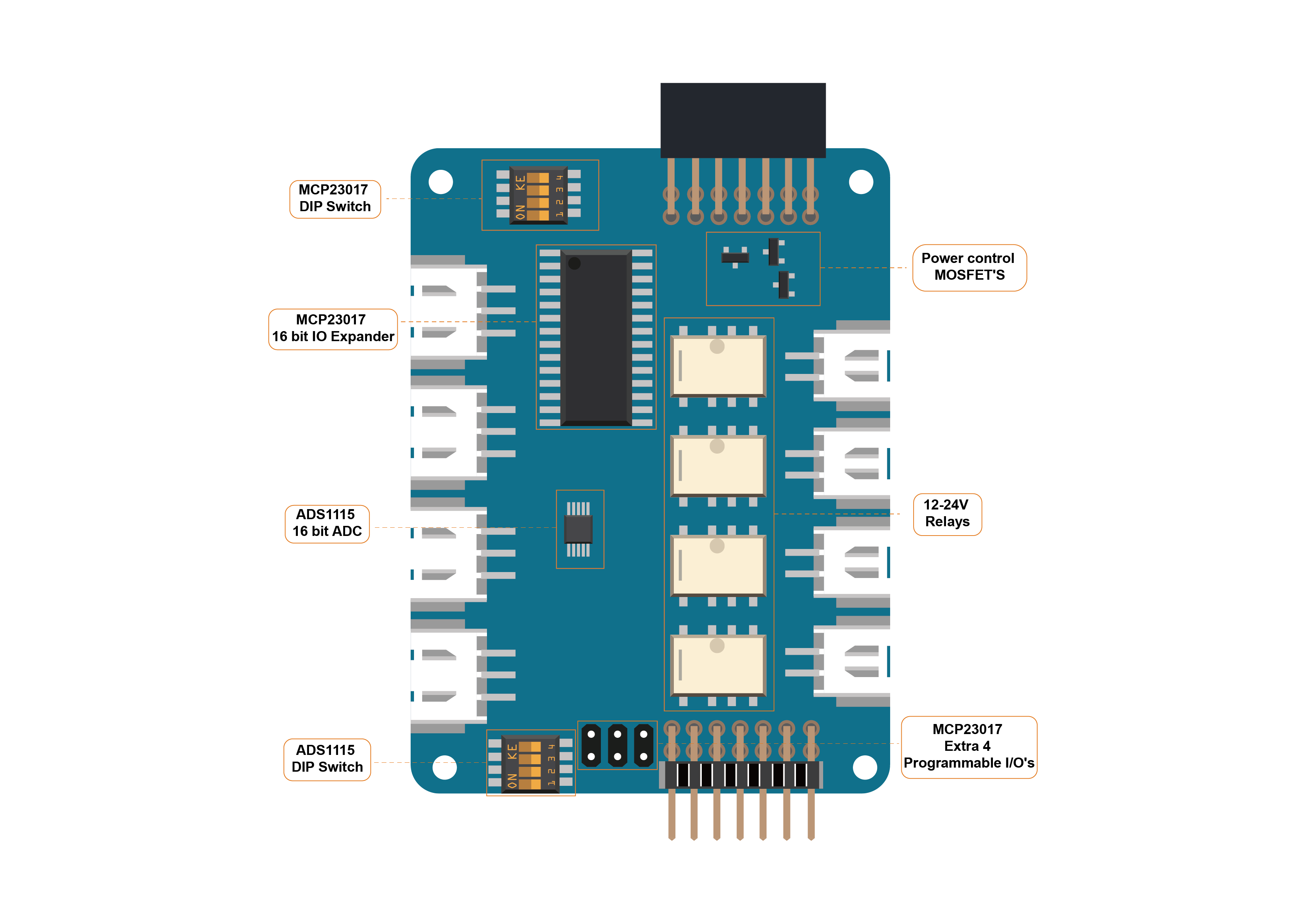
The Eduponics mini extension board designed using ADS1115 for ADC support and MCP23017 for GPIO control with some advance functionalities such as interrupt on change and precise analog data reading, the board allows to connect extra 4 analog data sensors and 4 digital output devices with 12V support.
While the Eduponics Mini ESP32 board allows to connect only one pump and one soil moisture sensor, we've decided to develop a custom HAT (Hardware Attached on Top) to enhance the Eduponics Mini functionalities by adding extra 4 soil moisture sensors and extra 4 pumps.
Features
If we use simple words: the extension board allows us to control extra 4 plants (total of 5 plants) at the same time.
If we go with deeper explanation, the sensors aren't necessary need to be soil moisture sensors or pumps, it can be any analog or digital sensors that needs to be controlled using the Eduponics Mini (or any other micro-controller), giving you access to extra 4 relays and another 4 open IOs (input / output) and extra 4 analog sensors control.
This is really great addition not just to the Eduponics Mini ESP32 board but also to other microcontrollers such as Raspberry Pi that needs extra IO pins or analog reading which it's lack of.
Here is the detailed features that the Eduponics Mini extension board can offer you:
- ADS1115 16 bit ADC chipset, precise analog data reading
- MCP23017 IO chipset, allows to control extra 8 IO (input or output) devices
- External interrupt pins on data change for MCP23017
- External interrupt alert on analog data changes for ADS1115
- 4 Relay modules with XH2.54 connectors, 5V-24V support
- I2C interface - only 2 pins required
- 12-24V output for the relay modules
- MOSFETs to control the main power and the power for each analog input
- Arduino, Raspberry Pi & ESP32 and other controllers compatible
12V-24V are not the same as 5V input
The Eduponics mini has 2 pins one is used as 12V pin goes from the DC adapter to the relay directly allows the relay to control pumps that rated higher than 5V, the other pin is 5V which gives power to the ESP32 and other ICs.
DO NOT connect voltage higher than 5V to the pin rated as 5V as this WILL damage your Eduponics extension board and/or your Eduponics mini. The 12V-24V are designed to be isolated and wired through the relays ONLY and are meant to control external sensors and modules that require such voltage.
Default address might be wrong for first batch (CrowdSupply)
If you purchased the product through CrowdSupply on the first batch, your extension board might state "MCP23017 default address: 0x20" in fact, the default address is 0x27. But don't you worry! this have no effect on your product at all, just make sure to note the default address if you haven't played around with the switches is 0x27 instead of 0x20.
ADS1115 16-Bit ADC
The Eduponics Mini Built-in ADC works pretty well but for the extension board we've decided to use ADS1115 to increase the precision, the ADS1115 provides 16-bit precision at 860 samples/second over the I2C protocol, the ADC includes a programmable gain amplifier, up to x16, to help boost up smaller single/differential signals to the full range
A micro-computer like Raspberry Pi for example doesn't have built-in ADC (analog to digital converter) as well as the pins might be occupied or limited, by using I2C we only need 2 pins and using the ADS1115 we can add analog capabilities to boards that lack of it.
Features
Here are some of the specific features of the ADS1115:
- Wide supply range: 2.0V to 5.5V
- Low current consumption: Continuous Mode: Only 150µA Single-Shot Mode: Auto Shut-Down
- Internal oscillator
- Internal PGA
- I2C Interface
For the complete information, check the ADS1115 data sheet: ADS1115 datasheet
ADS1X15 library
Make sure micropython-eduponics is installed through upip
For our Python code, we will need to import eduponics library, make sure you followed the introduction guide on installing the library on the ESP32 Eduponics Mini board.
Below is the MicroPython library to control and configure the ADS1115 functionalities using the Eduponics Mini board and micropython-eduponics library, in the following example we are going to use a single soil moisture input in ADC(0).
let's use it to to get the analog sensors data (both raw and voltage), voltage can be sometimes useful to create some other conversion techniques or use it for data collection purposes. We will configure I2C address on SCL pin 33 and SDA pin 32 as this is the pins the extension board connected to, then we will use the default 0x48 I2C address and set gain to 1 (default)
When reading analog, current will flow. When not reading - current will not flow
a cool feature we have built-in inside the ADS1X15 library is to auto-control the MOSFETs, when we test data through the ADS the MOSFETs will open, when we finish testing the MOSFETs will close. this allows us to both save power and use sensors together that otherwise might have a conflict.
We will read the analog data from the sensors every second and print them into the terminal screen.
For the Arduino code, we need to download and install the following library: ADS1115 Arduino Library
"""
MicroPython BMCP23017 Eduponics mini extension board - Soil moisture demo
https://github.com/STEMinds/eduponics-mini
MIT License
Copyright (c) 2020 STEMinds

Permission is hereby granted, free of charge, to any person obtaining a copy
of this software and associated documentation files (the "Software"), to deal
in the Software without restriction, including without limitation the rights
to use, copy, modify, merge, publish, distribute, sublicense, and/or sell
copies of the Software, and to permit persons to whom the Software is
furnished to do so, subject to the following conditions:
The above copyright notice and this permission notice shall be included in all
copies or substantial portions of the Software.

THE SOFTWARE IS PROVIDED "AS IS", WITHOUT WARRANTY OF ANY KIND, EXPRESS OR
IMPLIED, INCLUDING BUT NOT LIMITED TO THE WARRANTIES OF MERCHANTABILITY,
FITNESS FOR A PARTICULAR PURPOSE AND NONINFRINGEMENT. IN NO EVENT SHALL THE
AUTHORS OR COPYRIGHT HOLDERS BE LIABLE FOR ANY CLAIM, DAMAGES OR OTHER
LIABILITY, WHETHER IN AN ACTION OF CONTRACT, TORT OR OTHERWISE, ARISING FROM,
OUT OF OR IN CONNECTION WITH THE SOFTWARE OR THE USE OR OTHER DEALINGS IN THE
SOFTWARE.
"""

from eduponics import mcp23017,ads1x15
from machine import I2C, Pin
import time

# IO12 reserved for powering the board, define it
power = Pin(12, Pin.OUT)
# activate the board
power.value(1)

# make sure to wait enough time for the board to wakeup
time.sleep(0.1)

# define i2c connection to the extension board
i2c = I2C(scl=Pin(33), sda=Pin(32))

# setup adc for the extension board (default address for MCP might be 0x20)
ads_address = 0x48
mcp_address = 0x27
gain = 1

adc = ads1x15.ADS1115(i2c=i2c, address=ads_address,mcp_address=mcp_address, gain=gain)

# set max val and min val of the sensor
# this requires manual calibration
# minVal get be recieved by putting the sensor submerged in the water
# maxVal can be recieved by making sure the sensor is dry in the clear air
minVal = 710
maxVal = 4095

def value_in_percentage(val):
    # scale the value based on maxVal and minVal
    scale = 100 / (minVal - maxVal)
    # get calculated scale
    normal_reading = ("%s%s" % (int((val - maxVal) * scale),"%"))
    # we can also get inverted value if needed
    inverted_reading = ("%s%s" % (int((minVal - val) * scale),"%"))
    # for this example we'll return only the normal reading
    return normal_reading

# get voltage
adc_read = adc.read(0)
# get sensor value
voltage = adc_read["voltage"]
value = adc_read["raw"]
# print the analog results (moisture)
print("sensor value: %s" % value)
print("sensor value in percentage: %s" % value_in_percentage(value))
// I2C device class (I2Cdev) demonstration Arduino sketch for ADS1115 class
// Example of reading two differential inputs of the ADS1115 and showing the value in mV
// 2016-03-22 by Eadf (https://github.com/eadf)
// Updates should (hopefully) always be available at https://github.com/jrowberg/i2cdevlib
//
// Changelog:
//     2016-03-22 - initial release

/* ============================================
I2Cdev device library code is placed under the MIT license
Copyright (c) 2011 Jeff Rowberg
Permission is hereby granted, free of charge, to any person obtaining a copy
of this software and associated documentation files (the "Software"), to deal
in the Software without restriction, including without limitation the rights
to use, copy, modify, merge, publish, distribute, sublicense, and/or sell
copies of the Software, and to permit persons to whom the Software is
furnished to do so, subject to the following conditions:
The above copyright notice and this permission notice shall be included in
all copies or substantial portions of the Software.
THE SOFTWARE IS PROVIDED "AS IS", WITHOUT WARRANTY OF ANY KIND, EXPRESS OR
IMPLIED, INCLUDING BUT NOT LIMITED TO THE WARRANTIES OF MERCHANTABILITY,
FITNESS FOR A PARTICULAR PURPOSE AND NONINFRINGEMENT. IN NO EVENT SHALL THE
AUTHORS OR COPYRIGHT HOLDERS BE LIABLE FOR ANY CLAIM, DAMAGES OR OTHER
LIABILITY, WHETHER IN AN ACTION OF CONTRACT, TORT OR OTHERWISE, ARISING FROM,
OUT OF OR IN CONNECTION WITH THE SOFTWARE OR THE USE OR OTHER DEALINGS IN
THE SOFTWARE.
===============================================
Wiring the ADS1115 Module to an Arduino UNO
ADS1115 -->  UNO
  VDD        5V
  GND        GND
  SCL        A5 (or SCL)
  SDA        A4 (or SDA)
  ALRT       2
*/

#include "ADS1115.h"

ADS1115 adc0(0x48);

// Wire ADS1115 ALERT/RDY pin to pin 25
const int alertReadyPin = 25;

void setup() {
    //I2Cdev::begin();  // join I2C bus
    Wire.begin(33,32);
    Serial.begin(115200); // initialize serial communication

    Serial.println("Testing device connections...");
    Serial.println(adc0.testConnection() ? "ADS1115 connection successful" : "ADS1115 connection failed");

    adc0.initialize(); // initialize ADS1115 16 bit A/D chip

    // We're going to do single shot sampling
    adc0.setMode(ADS1115_MODE_SINGLESHOT);

    // Slow things down so that we can see that the "poll for conversion" code works
    adc0.setRate(ADS1115_RATE_8);

    // Set the gain (PGA) +/- 4.096V
    // Note that any analog input must be higher than –0.3V and less than VDD +0.3
    adc0.setGain(ADS1115_PGA_4P096);
    // ALERT/RDY pin will indicate when conversion is ready

    pinMode(alertReadyPin,INPUT_PULLUP);
    adc0.setConversionReadyPinMode();

    // To get output from this method, you'll need to turn on the
    //#define ADS1115_SERIAL_DEBUG // in the ADS1115.h file
    #ifdef ADS1115_SERIAL_DEBUG
    adc0.showConfigRegister();
    Serial.print("HighThreshold="); Serial.println(adc0.getHighThreshold(),BIN);
    Serial.print("LowThreshold="); Serial.println(adc0.getLowThreshold(),BIN);
    #endif
}

/** Poll the assigned pin for conversion status
 */
void pollAlertReadyPin() {
  for (uint32_t i = 0; i<100000; i++)
    if (!digitalRead(alertReadyPin)) return;
   Serial.println("Failed to wait for AlertReadyPin, it's stuck high!");
}

void loop() {

    // The below method sets the mux and gets a reading.
    adc0.setMultiplexer(ADS1115_MUX_P0_NG);
    adc0.triggerConversion();
    pollAlertReadyPin();
    Serial.print("A0: "); Serial.print(adc0.getMilliVolts(false)); Serial.print("mV\t");

    adc0.setMultiplexer(ADS1115_MUX_P1_NG);
    adc0.triggerConversion();
    pollAlertReadyPin();
    Serial.print("A1: "); Serial.print(adc0.getMilliVolts(false)); Serial.print("mV\t");

    adc0.setMultiplexer(ADS1115_MUX_P2_NG);
    adc0.triggerConversion();
    pollAlertReadyPin();
    Serial.print("A2: "); Serial.print(adc0.getMilliVolts(false)); Serial.print("mV\t");

    adc0.setMultiplexer(ADS1115_MUX_P3_NG);
    // Do conversion polling via I2C on this last reading:
    Serial.print("A3: "); Serial.print(adc0.getMilliVolts(true)); Serial.print("mV");

    Serial.println(digitalRead(alertReadyPin));
    delay(500);
}
MCP23017 16-bit I/O Expander
How can we control 4 relays without taking up 4 pins (excluding GND and VCC pins)? Simply use the MCP23017 I/O expander that uses I2C for communication (just 2 pins!)
the MCP23017 can control up to 8 IO ports: 4 of the IO pins are reserved for the relays those cannot be re-wired as input or any other purposes, for the other 4 IO pins we've made pins available to connect any other extra sensors. Except that, the Eduponics Mini also has available IO ports for use which are not taken by any other application.
Features
All the MCP23017 pins can be used for either input or output and they even offer some advance features such as external interrupt on I/O changes, the complete feature list includes:
- 16-Bit Bidirectional I/O Ports
- High-Speed I2C Interface
- Control up to eight IO devices
- Configurable interrupt output pins
To learn more, feel free to refer to the data sheet: MCP23017 data sheet
MCP23017 library
Make sure micropython-eduponics is installed through upip
For our Python code, we will need to import eduponics library, make sure you followed the introduction guide on installing the library on the ESP32 Eduponics Mini board.
For the Arduino demo - you'll need to install the arduino-mcp23017 library: arduino-mcp23017
In order to test the following example, make sure you have micropython-eduponics library installed through uPip:
#Copyright (c) 2020 Roni Gorodetsky for STEMinds
#Website: https://steminds.com

#Permission is hereby granted, free of charge, to any person obtaining a copy
#of self software and associated documentation files (the "Software"), to deal
#in the Software without restriction, including without limitation the rights
#to use, copy, modify, merge, publish, distribute, sublicense, and/or sell
#copies of the Software, and to permit persons to whom the Software is
#furnished to do so, subject to the following conditions:

#The above copyright notice and self permission notice shall be included in
#all copies or substantial portions of the Software.

#THE SOFTWARE IS PROVIDED "AS IS", WITHOUT WARRANTY OF ANY KIND, EXPRESS OR
#IMPLIED, INCLUDING BUT NOT LIMITED TO THE WARRANTIES OF MERCHANTABILITY,
#FITNESS FOR A PARTICULAR PURPOSE AND NONINFRINGEMENT. IN NO EVENT SHALL THE
#AUTHORS OR COPYRIGHT HOLDERS BE LIABLE FOR ANY CLAIM, DAMAGES OR OTHER
#LIABILITY, WHETHER IN AN ACTION OF CONTRACT, TORT OR OTHERWISE, ARISING FROM,
#OUT OF OR IN CONNECTION WITH THE SOFTWARE OR THE USE OR OTHER DEALINGS IN
#THE SOFTWARE.

from eduponics import mcp23017
from machine import I2C, Pin
import time

# IO12 reserved for powering the board, define it
power = Pin(12, Pin.OUT)
# activate the board
power.value(1)

# make sure to wait enough time for the board to wakeup
time.sleep(0.1)

# define i2c connection to the extension board
i2c = I2C(scl=Pin(33), sda=Pin(32))

# initialize relay object (default address might be 0x20)
relays = mcp23017.Relays(i2c, address=0x27)

# open relays one by one
for i in range(0,4):
    relays.open(i)
    time.sleep(1)

# close all relays one by one
for i in range(0,4):
    relays.close(i)
    time.sleep(1)

# open all relays
relays.open_all()

time.sleep(3)

# close all relays
relays.close_all()
/**
 * On every loop, the state of the port B is copied to port A.
 *
 * Use active low inputs on port A. Internal pullups are enabled by default by the library so there is no need for external resistors.
 * Place LEDS on port B for instance.
 * When pressing a button, the corresponding led is shut down.
 *
 * You can also uncomment one line to invert the input (when pressing a button the corresponding led is lit)
 */
#include <Wire.h>
#include <MCP23017.h>

#define MCP23017_ADDR 0x20
MCP23017 mcp = MCP23017(MCP23017_ADDR);

void setup() {
    Wire.begin(33,32);
    Serial.begin(115200);

    mcp.init();

    mcp.portMode(MCP23017Port::A, 0); //Port A as output
    mcp.portMode(MCP23017Port::B, 0); //Port B as output
    mcp.portMode(MCP23017Port::C, 0); //Port C as output
    mcp.portMode(MCP23017Port::D, 0); //Port D as output

    mcp.writeRegister(MCP23017Register::GPIO_A, 0x00);  //Reset port A
    mcp.writeRegister(MCP23017Register::GPIO_B, 0x00);  //Reset port B
    mcp.writeRegister(MCP23017Register::GPIO_C, 0x00);  //Reset port C
    mcp.writeRegister(MCP23017Register::GPIO_D, 0x00);  //Reset port D
}

void loop() {
    // open relay A
    mcp.writePort(MCP23017Port::A, 1);
    delay(500);
    // open relay B
    mcp.writePort(MCP23017Port::B, 1);
    delay(500);
    // open relay C
    mcp.writePort(MCP23017Port::C, 1);
    delay(500);
    // open relay D
    mcp.writePort(MCP23017Port::D, 1);
    delay(500);
    // close relay A
    mcp.writePort(MCP23017Port::A, 0);
    delay(500);
    // close relay B
    mcp.writePort(MCP23017Port::B, 0);
    delay(500);
    // close relay C
    mcp.writePort(MCP23017Port::C, 0);
    delay(500);
    // close relay D
    mcp.writePort(MCP23017Port::D, 0);
    delay(500);
}