WS2812B RGB LED
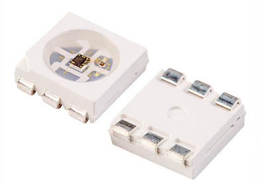
WS2812 is an intelligent control LED light source module with integrated RGB chip circuit at a 5050 size component package. Inside it includes intelligent digital port data latch and signal reshaping amplification drive circuit as well as a precision internal oscillator effectively ensuring the pixel point light color height will always be consistent.
Specifications
- Control circuit and RGB chip are integrated in a 5050 size package.
- Built-in signal reshaping circuit, after wave reshaping to the next driver, ensure wave-form distortion not accumulate.
- Built-in electric reset circuit and power lost reset circuit.
- Each pixel (total of three primary colors) can achieve a 0 to 256 on scale of brightness, which results in 16777216 color display options, and scan frequency of no less than 400Hz/s.
- Cascading port transmission signal by single line. (one pin can control the LED and colors changes)
- Data transmission speed of 800Kbps, Very fast and very accurate.
The complete data sheet of the WS2812B RGB can be viewed here: WS2812B RGB data sheet on parallax.com
Possible applications
You might think what does RGB LED has to do with Smart agriculture / automatic watering or anything regarding this kind of kit? Well, sometimes we could use an LED or two for indication purposes - why not use an RGB LED with thousands of colors possibility to indicate different state for each thing we do? for example:
- Alert indication if something goes wrong
- Connection status (MQTT / Wifi Connection) to show us the connection state
- Sensors state (i.e: red is bad, yellow warning, green is good)
- Blinking and animation for fun
RGB LED can be very useful specially for debugging without connecting to the kit by itself. for example, what if the network goes down and we want to know about it? we can set the RGB to "Red" if the connection is good, we can set it to "Green".
Hardware explanation
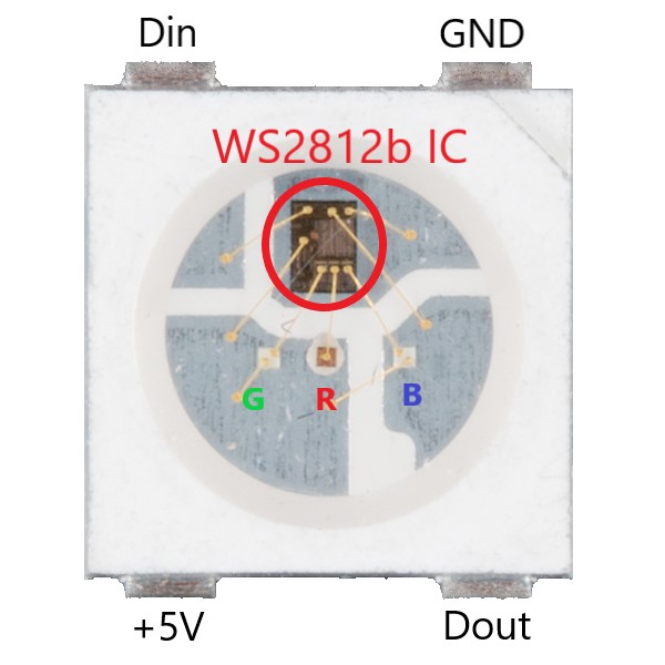
The cool thing about the WS2812B RGB LED is it's not just an LED (to be exact, 3 LEDs) but it includes a tiny IC (integrated circuit) inside that allows us to control the LED state using a single IO pin. The RGB color can be manipulated using a simple PWN commands, if you'd like to connect multiple WS2812B LEDs that can also be archived and guess what? with just a single IO pin!
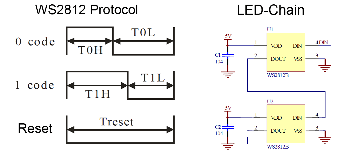
We can add as many as we want and connect them together in series, in the protocol each one will have a location starting from 0 up to n (number of LED's we have) in our program, we will control the WS2812B that is soldered on board, if you'd like to connect more LED's you'd need to get a strip and connect them to the IO expansion.
RGB LEDs are not suitable for plants growth
You might think you can use WS2812B RGB LED strip as a light growth, the truth is you can't. the spectrum and the wavelength of the RGB LED's not suitable for plants however you can find suitable LED's strip with the right light spectrum and wavelength for plants growth - just not the WS2812B LED strip.
Software explanation
The MicroPython includes a built-in library called "neopixel" which we can use to control our WS2812B RGB LED, the syntax is fairly simple.
First, we'll need to define to which IO pin the neopixel is connected - in our case it's pin 14, as a second argument (where we see 1) we need to define how many neopixels (RGB LEDs) do we have, our board only includes one so we write 1 as argument.
Next, we'll define the color we want for pixel at place 0 which is the first (and in our case the only) LED we'll use.
the colors are made from 3 arguments: red, green, blue. where the values goes from 0 to 255 which indicates the brightness of the color (0 empty and 255 is the brightest)
We can use a website such as Rapidtables to find different RGB codes that we can use to change the color in our LED.
The example below will turn the LED into red (full brightness) then green and then blue, finally we'll set all colors to 0 in order to turn the LED off.
import machine, neopixel
import time

# Configure the RGB LED at IO pin 14 (1 indicates 1 LED)
np = neopixel.NeoPixel(machine.Pin(14), 1)

np[0] = (255, 0, 0) # set to red, full brightness
np.write() # save changes
time.sleep(1)
np[0] = (0, 255, 0) # set to green, full brightness
np.write() # save changes
time.sleep(1)
np[0] = (0, 0, 255) # set to blue, full brightness
np.write() # save changes
time.sleep(1)
np[0] = (0, 0, 0) # empty the LED colors (wipe)
np.write() # save changes
#include <Adafruit_NeoPixel.h>

#define PIN 14

// When we setup the NeoPixel library, we tell it how many pixels, and which pin to use to send signals.
// Note that for older NeoPixel strips you might need to change the third parameter--see the strandtest
Adafruit_NeoPixel pixels = Adafruit_NeoPixel(1, PIN, NEO_GRB + NEO_KHZ800);

void setup()
{
  pixels.begin(); // This initializes the NeoPixel library.
}

void loop()
{
  pixels.setPixelColor(0, pixels.Color(255, 0, 0)); // set to red, full brightness
  pixels.show(); // This sends the updated pixel color to the hardware.
  delay(1000);
  pixels.setPixelColor(0, pixels.Color(0, 255, 0)); // set to green, full brightness
  pixels.show(); // This sends the updated pixel color to the hardware.
  delay(1000);
  pixels.setPixelColor(0, pixels.Color(0, 0, 255)); // set to blue, full brightness
  pixels.show(); // This sends the updated pixel color to the hardware.
  delay(1000);
}